LTE Studies
Pathloss can now generate RSRP results for Local and Area Studies, and RSRQ results for Area Studies.
Equipment Parameters
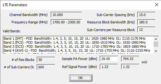
LTE Studies require a radio file to be specified with a valid LTE Channel Bandwidth. This bandwidth is used to determine parameters such as number of resource blocks and number of sub-carriers used for the calculation of RSRP and RSRQ.
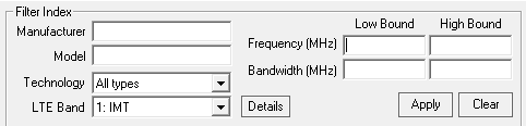
The equipment index now contains a Bandwidth column that can be used to filter the index. Radio files will have to be re-imported in to the equipment index in order to populate the bandwidth column.
The LTE Bandwidth filter can be used to filter the index to only show radios that can be used with that band. This is based on the channel bandwidth and the frequency. You can also click the details button to see the specific values used to filter.
The radio view also has an LTE Parameters button that can be used to check if the radio is valid for LTE, view the parameters and list of valid LTE bands. (Note: these controls are only visible for the PL6C and PL6T options.)

The following bands are listed as filter option:
| Band | Common Name | Mode | UL Freq. (MHz) | DL Freq. (MHz) | Duplex Spacing (MHz) | Supported BW (MHz) |
|---|---|---|---|---|---|---|
| 1 | IMT (2100) | FDD | 1920 – 1980 | 2110 – 2170 | 190 | 1.4, 3, 5, 10, 15, 20 |
| 2 | PCS (1900) | FDD | 1850 – 1910 | 1930 – 1990 | 80 | 1.4, 3, 5, 10, 15, 20 |
| 3 | DCS (1800) | FDD | 1710 – 1785 | 1805 – 1880 | 95 | 1.4, 3, 5, 10, 15, 20 |
| 4 | AWS-1 | FDD | 1710 – 1755 | 2110 – 2155 | 400 | 1.4, 3, 5, 10, 15, 20 |
| 5 | Cellular (850) | FDD | 824 – 849 | 869 – 894 | 45 | 1.4, 3, 5, 10, 15, 20 |
| 7 | IMT-E (2600) | FDD | 2500 – 2570 | 2620 – 2690 | 120 | 1.4, 3, 5, 10, 15, 20 |
| 8 | Extended GSM (900) | FDD | 880 – 915 | 925 – 960 | 45 | 1.4, 3, 5, 10, 15, 20 |
| 12 | Lower SMH (700) | FDD | 699 – 716 | 729 – 746 | 30 | 1.4, 3, 5, 10 |
| 13 | Upper SMH (700) | FDD | 777 – 787 | 746 – 756 | −31 | 5, 10 |
| 20 | Digital Dividend (800) | FDD | 832 – 862 | 791 – 821 | −41 | 5, 10, 15, 20 |
| 28 | APT (700) | FDD | 703 – 748 | 758 – 803 | 55 | 3, 5, 10, 15, 20 |
| 38 | IMT-E TD (2600) | TDD | 2570 – 2620 | N/A | 5, 10, 15, 20 | |
| 40 | S-Band TD (2300) | TDD | 2300 – 2400 | N/A | 5, 10, 15, 20 | |
| 41 | BRS TD (2500) | TDD | 2496 – 2690 | N/A | 5, 10, 15, 20 | |
| 66 | Extended AWS (1700) | FDD | 1710 – 1780 | 2110 – 2200 | 400 | 1.4, 3, 5, 10, 15, 20 |
| 71 | Digital Dividend (600) | FDD | 663 – 698 | 617 – 652 | −46 | 5, 10, 15, 20 |
RSRP Calculation
RSRP calculation can be set as the display criteria for Local and Area Studies. All base stations in the study must have valid LTE Radios in sectors to be included in the study. Reference power for the radio will be calculated and used to determine the RSRP.
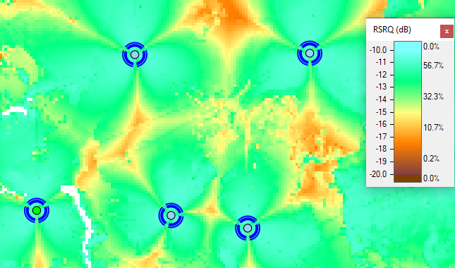
RSRQ Calculation
RSRQ can be set as the display criteria for Area Studies. All base stations should have valid LTE radios for the base stations sectors and the remote. This operation is similar to the existing CtoI calculation. in a given cell, the highest RSRP value is treated as the carrier.
interfering power from other base stations is determined by applying a filter improvement and then summing all the powers. If the radio files contains the necessary data to compute an filter improvement, this will be used. Otherwise, base station sector channel numbers will be used to reject powers from different channels. The receiver noise floor is also added to this total interfering level.
The carrier power is multiplied by the number of resource blocks. The ratio of this value to the total interfering level in the cell is the reported RSRQ.